|
I made a poor
man's backup switch. By welding a "bump" on the shift rod and
installing a pressure activated switch, I was able to turn on my
backup lights. The connections to my Northstar park/neutral
switch did not work well. |
Double-click to add photos
|
|
Back to the
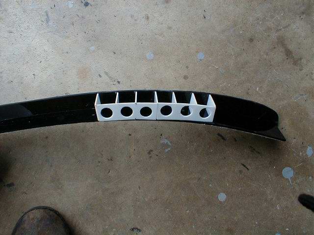
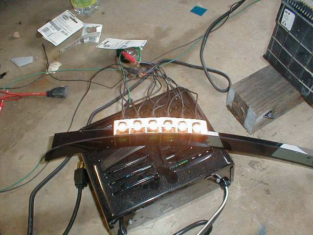
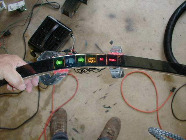
Car. I finished making my indicator lights. I built the light
boxes out of white plastic. After I got them put together,
the light reflected too much and the edges showed through the
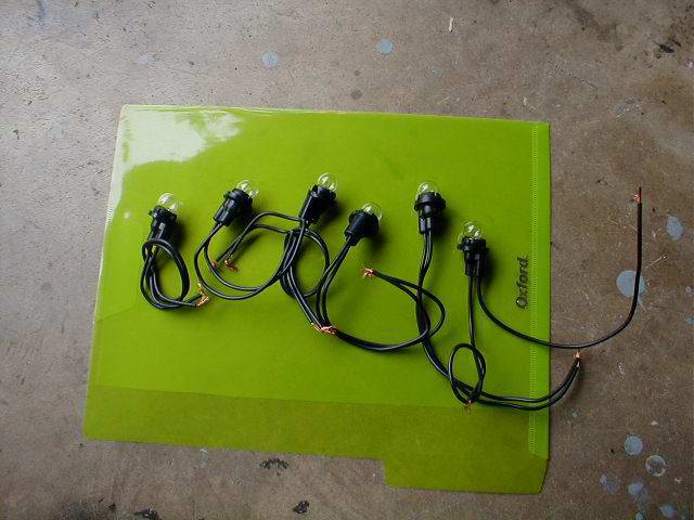
front so I went back and painted them black. I got 6 bulbs from
Ron Francis Wire Works to go in the sockets I made templates in
Word and printed them with white text. I used pieces of
transparent folders from Office Depot for the colors that I
wanted. It is not even in the same league as the ones that JC
did but they are functional. |
|
|
|
I completed the
dash dimmer switch to connect to the instrument panels and the
dome lights. I used the Fiero controls and mounted it below the
voltage meter. I had to install the door switches to operate the
dome lights. I actually ran the ground wire (what activates the
dome light) to a separate cut off switch so I can cut
power if I want to leave the doors open for a while and not
worry about running down the battery. |
|
|
| |
| On
to the instrument lights. The following pictures are from the
second one I built. The first assembly looked great. I had taken
the Fiero indicators from the Fiero instument cluster, glued
them in and the when the light was shined from the back they lit
up perfectly. Andy Bujtas had sent me his instructions on how he
had built his light boxes. I neglected the one area where he
mentioned he sealed the edges around the insert and 'let it dry'
before painting the outer area with black paint. When I did
this, the paint bled under the indictors and ruined the
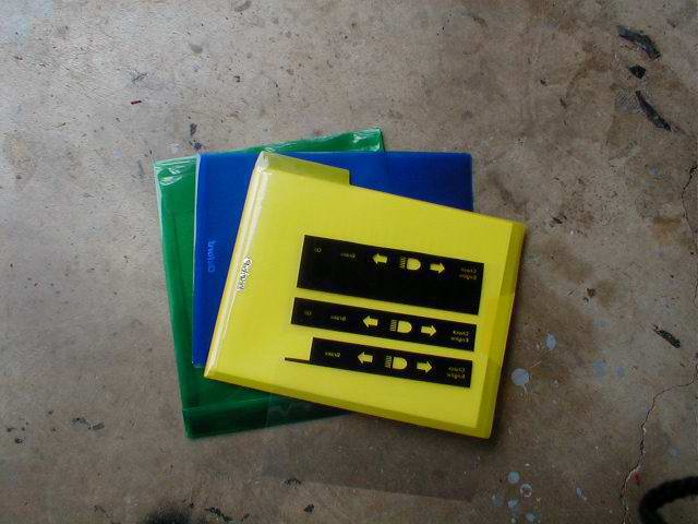
assembly. I have created a template in Word that I will print on
transparency stock on a laser printer. I will then use colored
film from these transparent folders to give me the color I want
and try again. The assembly itself is made from 1/8" smoke
plexiglass for the front and then I used 1/8" black for the
bottom. I should have used white as I need the reflecting
surface for the light box. I may do that on the second one.
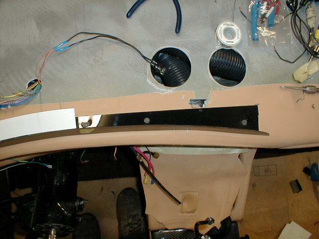
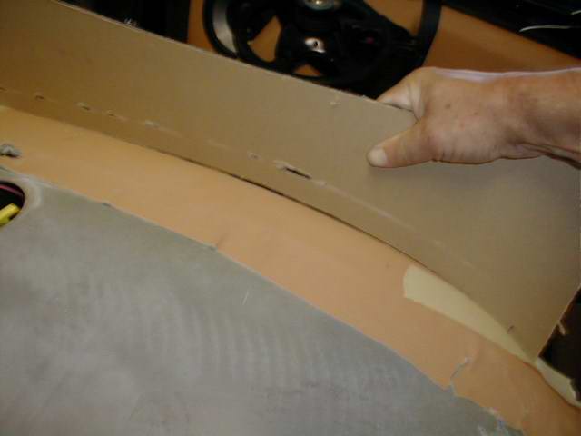
This involved
marking the curve of the dash both horizontally and then
matching the the vertical opening after I had cut the dash piece
out and reupholstered the front. You can see what it will look
like when I'm done, but the one doesn't have the lights in place
yet. Hopefully someone can learn from my mistakes. |
|
|
| |
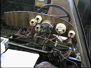
| I started on the instruments
wiring. I verified the Fiero wires by using the Fiero Plug on the back of
the Fiero Panel and checking the wires for turn signals, high beam, check
engine etc. I plan on using the graphics in my panel when I'm done. I have a
kenwood head unit that is a black panel when power is off. When power to the
car is on, it reverses for the controls. It retracts half way when you need
to insert a CD. Sounds pretty good with 6 speakers and the sub. |
|
|
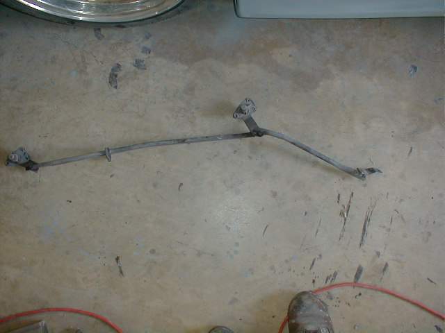
| Installed the wiper linkage.
A full day job.
|
|
|
| Started laying out the
instruments. I had some 1/4" Plexiglas that I decided to use until I got my
new carbon fiber pieces. I decided to go with the same size speedometer as
the tach. It is only 120 MPH. I may sell the Monster 160 speedometer and get
another Autometer white gauge that says 160. I made a wiring loom for
all the lights and gauges to simplify install later on. |
|
|
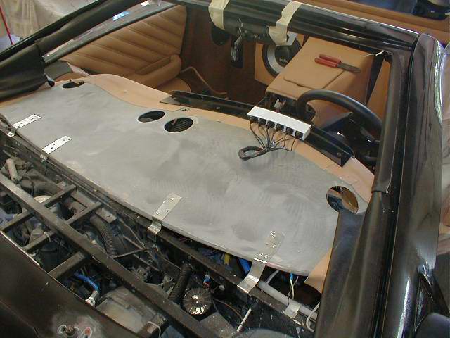
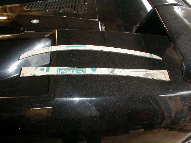
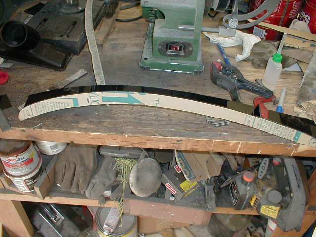
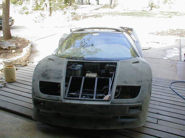
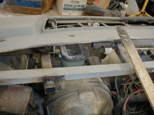
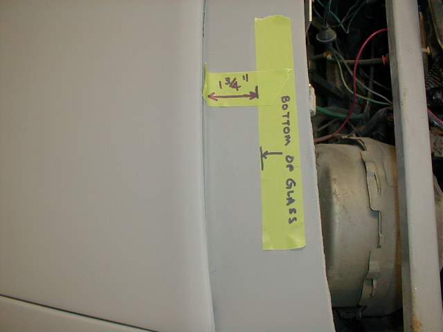
This was the test fit of the windshield to determine the bottom edge
of the glass.
|
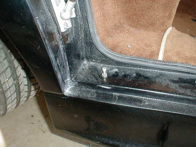
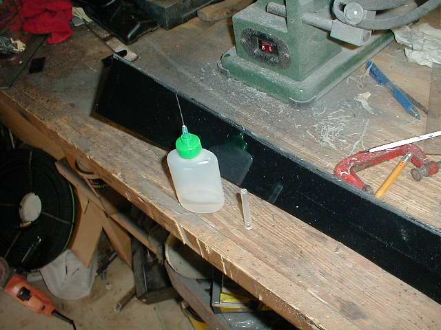
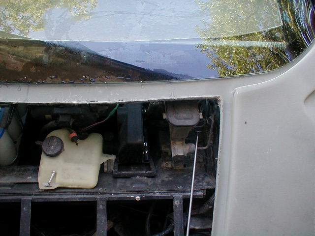
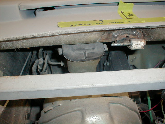
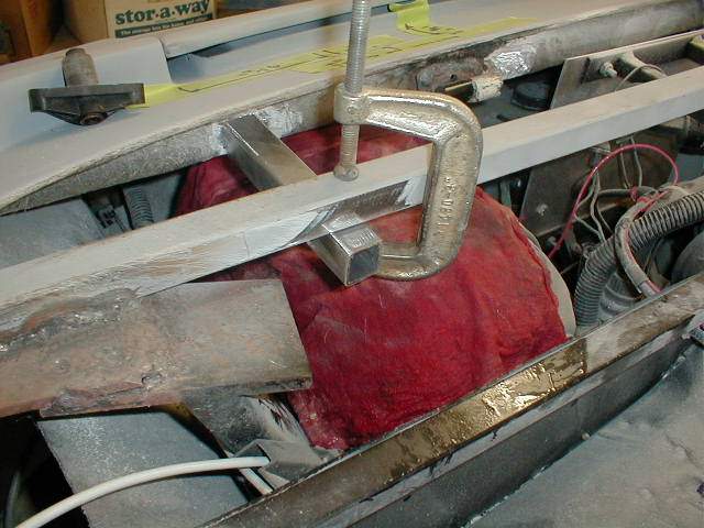
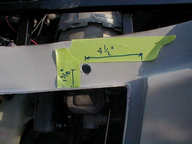
The bracket will go almost directly over the brake fluid reservoir.
This would have been much easier to do if I would have done it when I had
the body off. Because you need to cut the tubing out, it is necessary to
brace either side. I chose to tie it into a bar that I had between my two
door hinge brackets. AFter I had welded the two braces, I cut out the
center section. The bottom glass is about 2" from the lip of the trunk.
The actual location to drill the hole is 4 1/2" from the edge of the trunk
and 1 3/8" from the lip. I'll have more detail as I progress.
 |
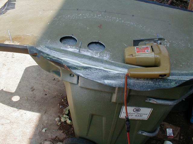
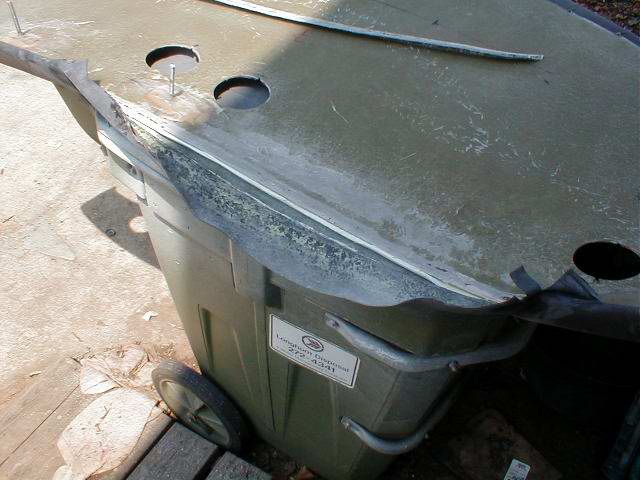
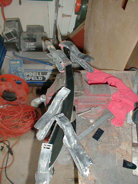
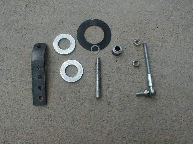
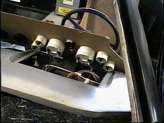
Started on the wiper motor connections so I could get the post in
place before I painted. First picture is the components that comes from
IFG. Next Pict is the Fiero wiper assembly for two wipers. Third picture
is just the section that I will be using. Forth picture is where You grind
off the top of the post so you can remove the shaft by punching it out.
You also have to cut off the vanes around the post.
  |
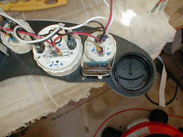
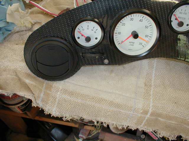
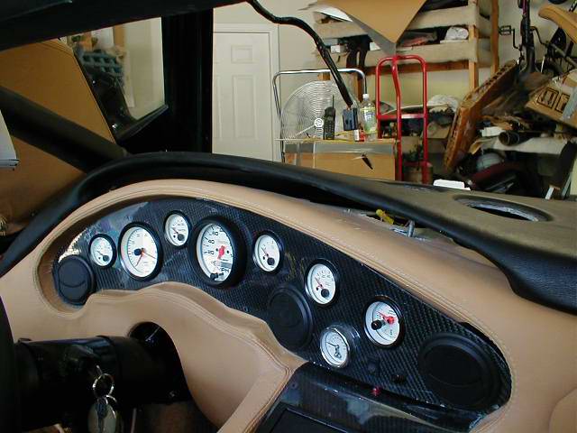
I temporarily mounted my gagues in a piece of 1/4" plywood so I could
do the wiring. You will notice that I have replaced the VDO 120mph
speedometer with an Autometer 5" 160mph speedometer. It will look
impressive when I am all done. The connections to the guages is fairly
straight forward. Take the existing Fiero pink and black wire in slot 9
and splice that into a power loop to all the power requirements on the
guages. Make a ground wire for all the guages and provide a good ground.
The fuel sending wire is the pink wire in slot 7 of the Fiero harness.
Still working on the Tach but I am making progress.
 |
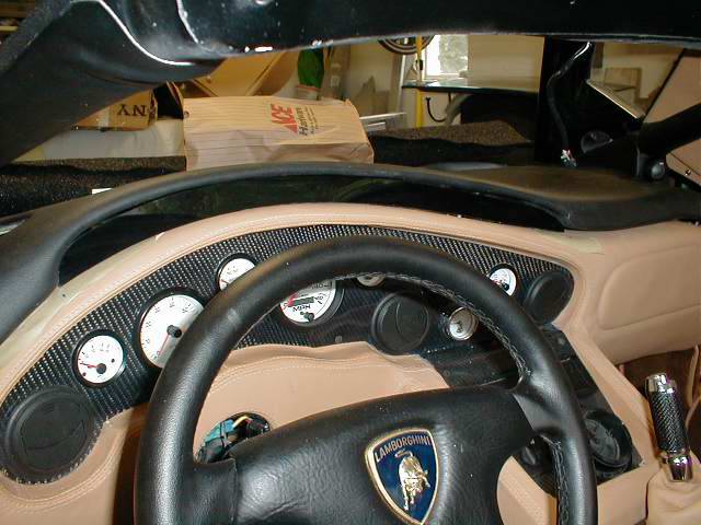
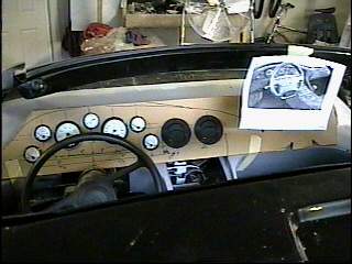
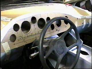
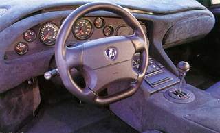
I started to layout the instruments but I want to have the newer style
dash. See picture below. It will involve making a whole new section that I
will have to upholster but I think that is something that I can do. I have
the same leather interior that is shown in the bottom two pictures. These
are from Jim Drew's car that he has listed under the For Sale button. You
can see the older style pod is quite high and the newer on gives much more
visibility.
|